
Savaria
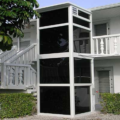
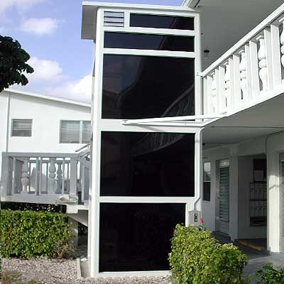
V-1504 Enclosed Vertilift

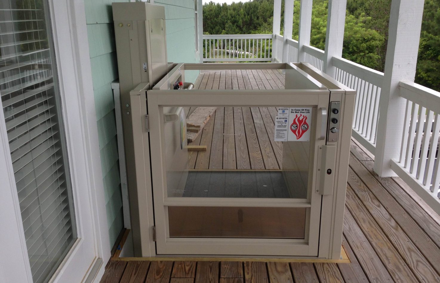
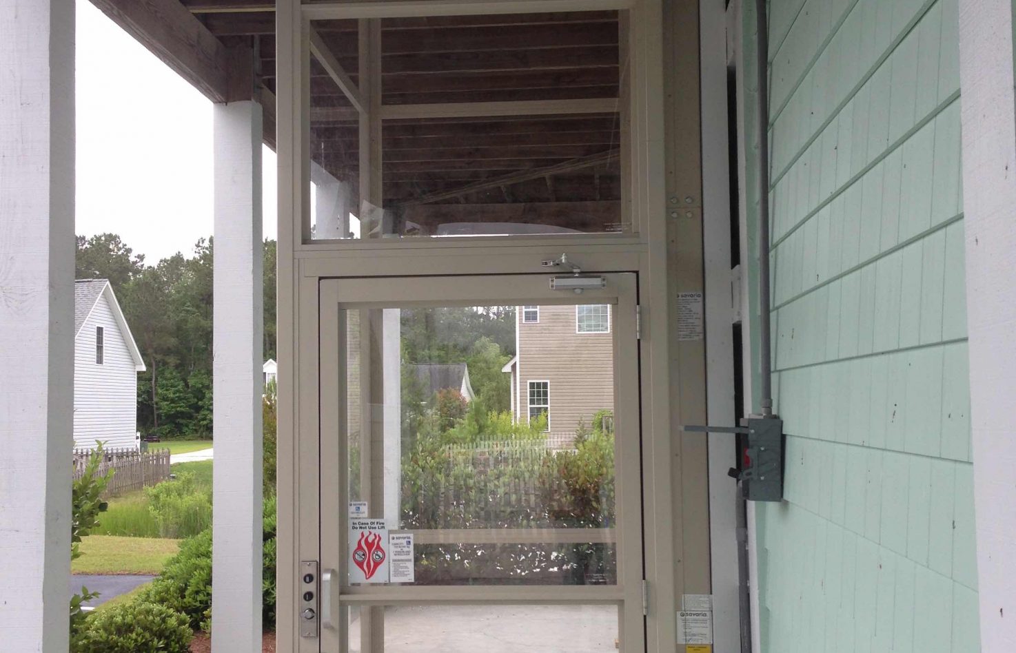
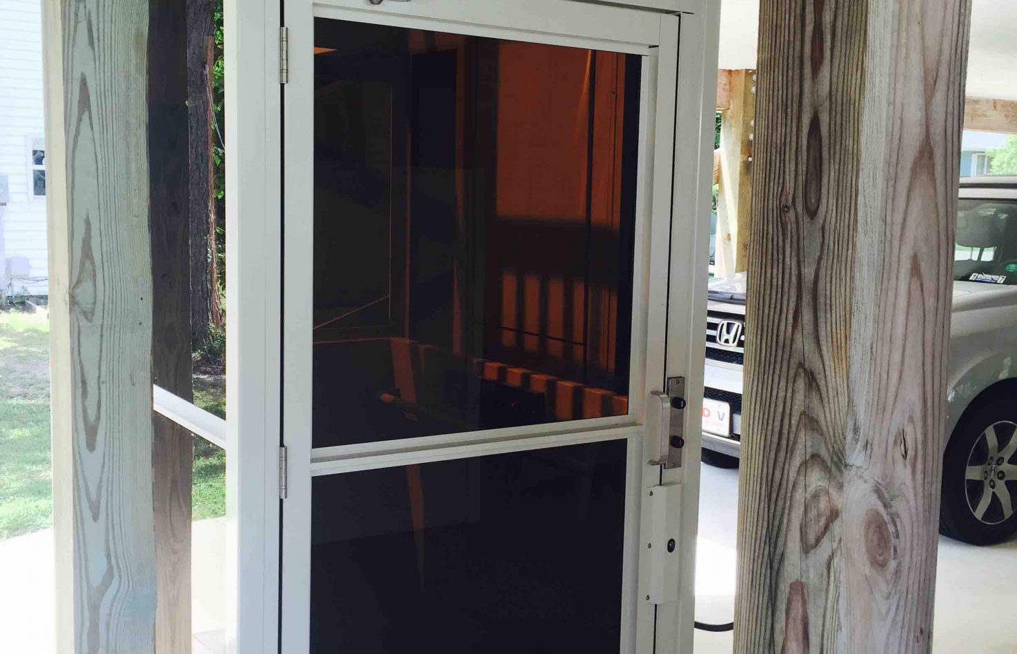
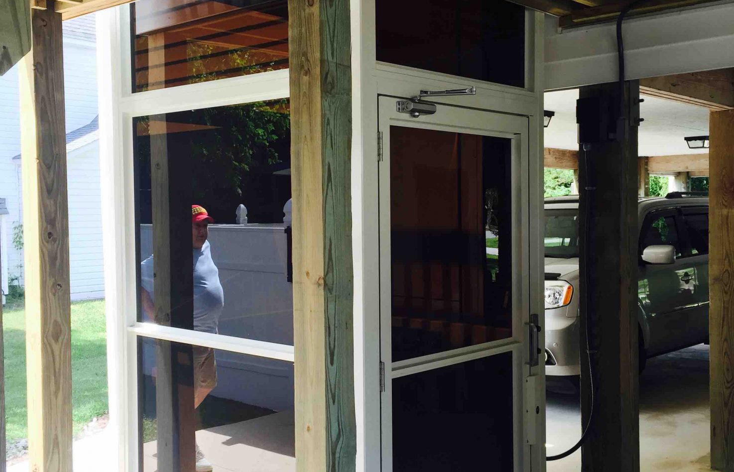
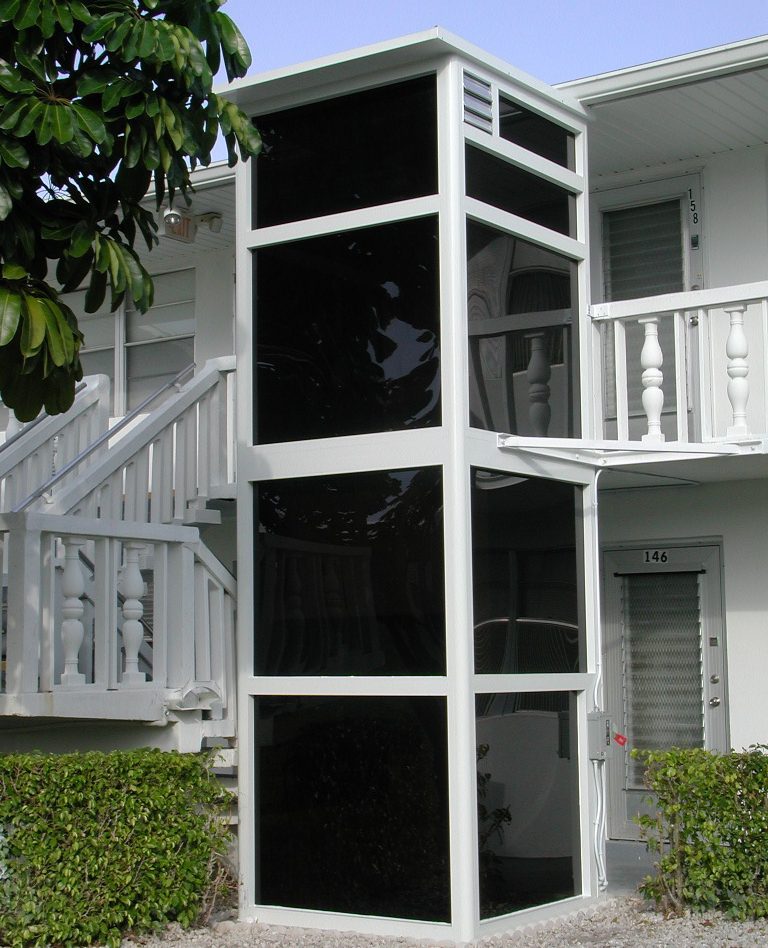
Do you own a condominium or beach home in the area? The fully-enclosed Vertilift is the perfect solution for easy transportation from one floor to the next. This version can be installed either on the inside or outside of your property and will be custom built to fit the structure’s specifications. The Vertilift meets all North Carolina state wind load requirements, as well as any other codes your building may have.
Like all other products from Liftavator, the fully enclosed Vertilift platform lift comes with a complete five-year warranty for your convenience and security. The fully-enclosed Vertilift saves you from having to build a shaft for the Vertilift if one is required. For more information, call us today.
Photos

Details
- Swift 20 ft/min hydraulic lift to carry a wheelchair and passenger up to 4 stops over 23′ of travel (code permitting)
- Often configured for use in a shaftway
- Array of optional paint colors; gates available with aluminum, acrylic or glass inserts, and with automatic opener
- ADA-compliant or custom platform sizes; same-side, straight-through or 90º entry and exit
- Drive system is located in tower so no machine room needed; operated by constant pressure controls
- For residential or commercial access; 750 lb capacity
- Suitable for indoor or outdoor use; also available with enclosure and luxury glass models
Specifications:
| Applications: | Residential, commercial, indoors, outdoors |
| Standard capacity: | 750 lb (340 kg) |
| Maximum travel distance: | 23' (7 m), subject to local code; commercial use in the USA limited to 12' to 14' (3.65 to 4.26 m) depending on the year of code enforced |
| Nominal speed: | 20 ft/min (0.1 m/s) |
| Drive/motor: | 2:1 chain hydraulic, 3 hp (2.2 kW), gear-type motor |
| Minimum pit: | 3" (76.2 mm) |
| Power supply: | 120 VAC, 20 amp, single phase, 60 Hz |
Features:
- Flexible design and feature options: Highly customizable: can be built to suit virtually any home or commercial project.
- Quiet and reliable hydraulic drive: Smooth start, stop and overall ride that works dependably.
- Machine roomless: Enclosed drive system means no machine room is required, making the installation process easier.
- Other standard features: 36" x 54" standard platform, continuous pressure button operation, modular rail construction for easy construction, handrail.
- Standard finish: Beige powder-coat paint.
- Safety features: Emergency stop button on car, non-skid platform, manual lowering device, 42 1/8" (1070 mm) side panels, keyed car buttons and keyed call stations, safety brake, door locks.
Options:
- Optional configurations: Type 1, 2, 3, 4 and 5
- Platform sizes: W36" x L48" (914 mm x 1219 mm), Type 1, 2, 3, 4, 5 | W36" x L54" (914 mm x 1371 mm), Type 1, 2, 3, 4, 5 | W36" x L60" (914 mm x 1524 mm) Type 1, 2, 3, 4, 5
- Custom sizes up to 42" x 60" (1067 mm x 1524 mm)
- Hoistway model (V-1504 standard): Can be configured for use in a shaftway by your local installer. For travel up to 23' (code permitting).
- Optional finishes: A wide array of powder-coat colors in gloss, semi gloss or textured finish are available, including custom color (see color chart).
- Other options: Up to 4 stops, commercial package including alarm, auto fold-up ramp, underpan obstruction sensors, platform gate, battery backup, keyless operation, keyed or keyless hall call (subject to type of application), low profile aluminum doors, steel ULC fire rated doors, wooden door, power gate and door operators, tempered glass inserts for doors, acrylic inserts for gate, GAL or Savaria WR-500 weather resistant lock, folding seat, 60 mm buttons, ADA hands-free phone.
Drawings
N/A
Planning Guide
The specification section is organized by placing information in three standard parts:
PART 1 – GENERAL Describes administrative and procedural requirements.
PART 2 – PRODUCTS Describes materials, products, and accessories to be incorporated into the construction project.
PART 3 – EXECUTION Describes how the products will be installed at the construction site.
PART 1 – GENERAL
1.01 RELATED DOCUMENTS
A. Drawings and general provisions of the Contract, including instructions to Bidders, Supplementary instructions to Bidders, General Conditions, Supplementary Instructions to Bidders, General Conditions, and Division 1 Specification Sections apply to work of this Section.
1.1 DESCRIPTION
A. Work described in this Section includes providing equipment, incidental material and labor required for complete, operable hydraulic platform lift installation. Where singular reference is made to lifts or lift components, such reference shall apply to number of lifts or components required to complete installation. This specification provides a broad outline of required equipment and does not describe the details of design and construction. Lifts shall be erected, installed, adjusted, tested and placed in operation by lift system manufacturer, or manufacturer’s authorized installer.
B. Lifts shall be in accordance with the ASME A17.1 Section 2000, ADA compliant including local codes and regulations except where specified otherwise.
1.2 PREPARATORY WORK BY OTHERS
A. The following preparatory work to receive the lifts specified in this Section is part of the work by others:
-
- Permanent 115 volt 20 Amp single phase power to operate lift to be provided from a lockable fused/cartridge type disconnect switch with auxiliary contacts for battery operation. Refer to drawings for permanent power specifications and location of disconnects. Temporary power may be provided to expedite installation of lift.
- Provide rough openings as per lift contractor’s shop drawings.
1.3 QUALITY ASSURANCE
A. Subcontractor Qualifications:
- Execute work of this section only by a company who has adequate product liability insurance.
- Skilled tradesmen must be employees of the installing contractor approved by the lift manufacturer, with demonstrated ability to perform the work on a timely basis.
B. Requirements of Regulatory Agencies:
- Fabricate and install work in compliance with applicable jurisdictional authorities.
- File shop drawings and submissions with local authorities as the information is made available. Company pre-inspection and jurisdictional authority inspections and permits are to be made on timely basis as required.
- Submit certification that platform lift system complies with current ADA requirements.
1.4 SUBMITTALS
A. SHOP DRAWINGS – the shop drawings shall show a complete layout of lifting equipment detailing dimensions and clearances as required.
B. Submit physical samples of all items requiring selection of color or finish.
1.5 WARRANTY
A. All material and components are guaranteed by Liftavator for a period of three (3) years. All labor is guaranteed by Liftavator for a period of ninety (90) days. Thereafter, Liftavator will repair or replace, at their option, any defects in materials or workmanship for a period of three (3) years. Labor, freight, and any incidental costs required to replace the defective part(s) are not included.
PART 2 – PRODUCTS
2.1 PLATFORM LIFT
A. Basic of specifications is a Liftavator VL-FE vertical platform lift model
with the following characteristics:- Rated Load ……………………………………………………………. 750 lbs.
- Rated Speed …………………………………………… 20 f.p.m. (nominal).
- Usable Car Dimensions ……………………………………….36”W x 54” L.
- Levels Serviced …………………………………………………………………2.
- Number of Openings …………………………………………………………..2.
- Car Access ……………………………………………………..Front/Rear Exit.
- Travel …………………………………………………………….Maximum 24’ 0”.
- Operations …………………………Constant pressure, anti-creep feature.
- Power Supply …………………………………………………..110v, 1 Phase.
- Drive System …………………………………………Direct Acting Hydraulic.
- Paint ……………………………………………………………..Urethane finish.
- Emergency Power …………………….Battery Operation/Down Direction.
- Controller ……………………………………….Electronic Free Relay Logic.
- Car Enclosure Type ……………………..Plexiglas panel inserts (Acrylic).
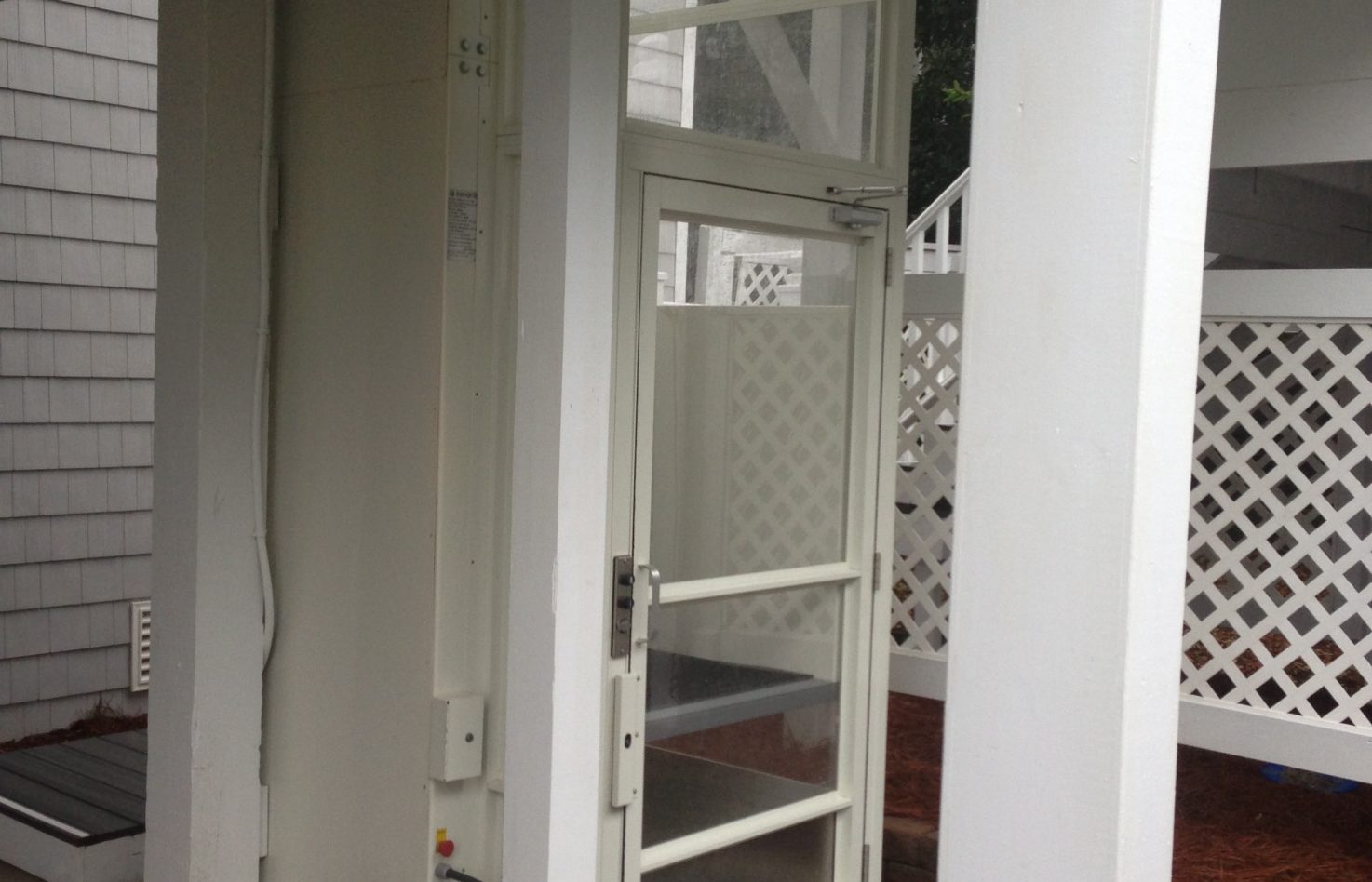
B. Car Enclosure:
- The enclosure shall have a steel frame with a urethane finish with acrylic panel inserts to a minimum of 42” above the upper landing.
- No platform gate required, to allow for ease of operation.
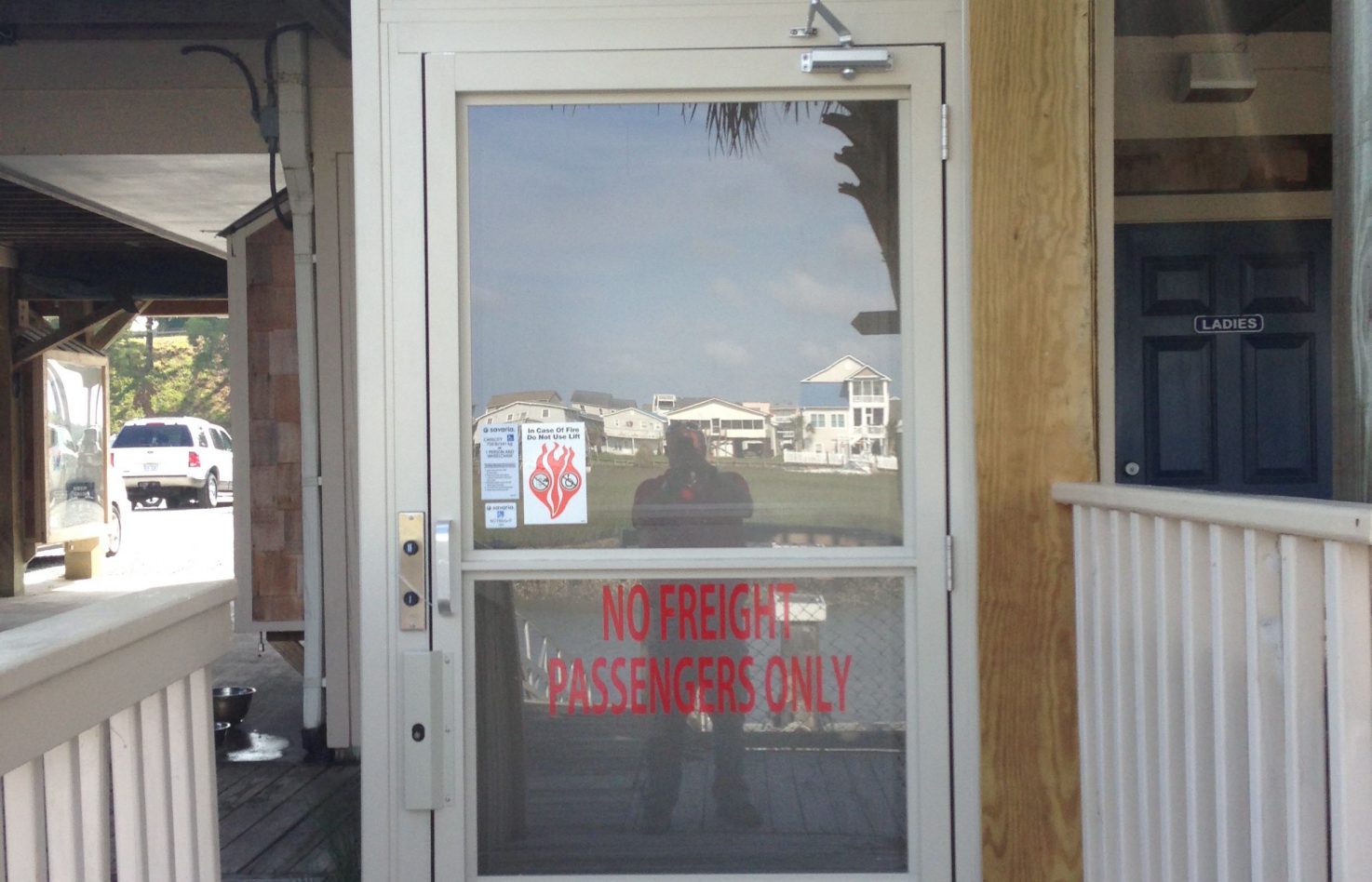
- Upper gate shall be 42” high x 34” clear open width, with acrylic inserts and shall be equipped with interlock, spring hinges and kick plate on both sides. Lower door shall be 80” high x 34” clear open width, with acrylic panel and shall be equipped with interlock, hydraulic closer.
- Lift shall have manufacturer’s standard non-skid flooring.
- The upper gate shall have an adjustable fascia with steel frame and metal insert that runs down to the pit.
- Doors and gates shall be flush mounted inside the hoistway as to avoid pinch points and shear hazards.
- Handrail: A single handrail with both ends returned to the wall shall be located on the control wall of the carriage.
Alternate: 48” acrylic extension at the upper landing with upper door 80” high x 34” clear open width and acrylic roof or dome.
2.2 CAR OPERATION
A. Car Operating Panel shall consist of constant pressure buttons or rocker switches, an emergency stop/alarm button, an on/off key switch and emergency light mounted on a removable stainless steel panel (Type 304 #4 Stainless Steel Finish).
B. Emergency Operation – The car shall be equipped with a battery operated light fixture, emergency battery lowering device and alarm in case of normal building supply failure. The battery shall be the rechargeable type with an automatic recharging system.
2.3 PUMPING UNIT AND CONTROL
A. The pumping unit and control shall be enclosed in the tower. The controller and pump unit shall be prewired and tested prior to shipment. The controller is to be electronic free with relay logic operations for ease of maintenance and service. This pump unit shall incorporate the following features:
- Smooth stops at each landing shall be an inherent feature.
- Adjustable pressure relief valve.
- Manually operable down valve to lower lift in the event of an emergency. This valve shall be activated from outside of the hoistway through a keyed box.
- Pressure gauge isolating valve, manually operable.
- Gate valve to isolate cylinder from pump unit.
- Electrical solenoid for down direction control.
- Emergency lowering by battery power, from the car control.
2.4 CYLINDER AND PLUNGER
A. The cylinder shall be constructed of steel pipe of sufficient thickness and suitable safety margin. The top of the cylinder shall be equipped with a cylinder head with an internal guide ring and self-adjusting packing.
B. The plunger shall be constructed of a steel shaft of proper diameter machined true and smooth. The plunger shall be provided with a stop electrically welded to the bottom to prevent the plunger from leaving the cylinder.
2.5 LEVELING DEVICE
A. The lift shall be provided with an anti-creep device which will maintain the carriage level within 1/2” of the top landing.
B. All limit switch and leveling device switches shall be located in a position to be inaccessible to unauthorized persons. They shall be located behind the mast wall and be accessible through removable panels. Micro-switches shall not be used.
2.6 CALL STATIONS
A. Provide door frame mount key controlled call stations for upper level and lower level on a stainless steel plate (Type 304 #4 stainless steel finish).
2.7 TERMINAL STOPPING DEVICES
A. Normal terminal stopping devices shall be provided at top and bottom of runway to stop the car positively and automatically. Micro-switches shall not be used.
2.8 GUIDE RAILS AND BRACKETS
A. Steel “C” guide rails and brackets shall be used to guide the platform and sling. Guide rails shall form part of the structural integrity of the unit and be integral to the mast enclosure, ensuring stability and minimum platform deflection when loaded.
2.9 CAR SLING
A. Car Sling shall be fabricated from steel tubing 44” high with adequate bracing to support the platform and car enclosure. Roller guide shoes shall be mounted on the top and bottom of the car sling to engage the guide rails. Guide shoes to be roller type with 3” diameter wheels. The car sling arms shall be detachable..
2.10 WIRING
A. All wiring and electrical connections shall comply with applicable codes. Insulated wiring shall have flame retardant and moisture proof outer covering and shall be run in conduit, or electrical wireways outside the unit enclosure. Quick disconnect harnesses shall be used.
PART 3 – EXECUTION
3.1 EXAMINATION
A. All site dimensions shall be taken to ensure that tolerances and clearances have
been maintained and meet local regulations.3.2 PREPARATION
A. Pre-inspect the construction and service requirements for work by others. These
requirements will be included in drawings, diagrams, engineering data sheets
and special instructions before the work commences.3.3 INSTALLATION
A. Install all the components of the lift system that are specified in this Section to
be provided, and that are required by jurisdictional authorities to license the lift.B. All installation work of this Section shall be performed by trained employees of
the lift contractor.C. Adjust lift for proper operation and clean unit thoroughly.
D. Instruct Owner’s Operations and Maintenance personnel in proper
trouble-shooting and maintenance procedures. Submit three (3) copies of
operating and maintenance manual.Click here to download the Fully Enclosed Vertilift CSI Specs
Warranty
Most Liftavator products have a standard warranty of three (3) years. Warranty periods of up to five (5) years are available for some products. For more specific information on warranty coverage, please contact us directly.